Minimelt II
Thermal Link
Tmax 206°C / 229°C / 260°C / 298°C / 318°C / Imax15A / slim design / very short reaction time / orientation independent mounting / temperature resistant ceramic housing / standard terminals
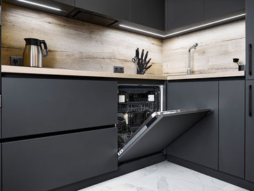
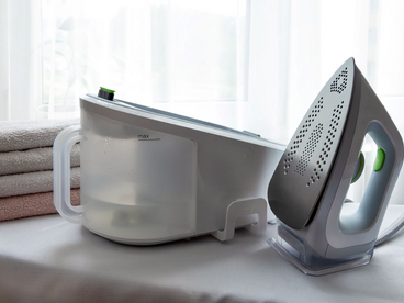
Properly installed, the thermal link type 155 131 may be used for applications where a maximum temperature must not be exceeded, for example in coffee makers, irons, dishwashers, dryers and to protect electric heating elements.
The thermal link has a melt solder insert in the mounting plate which is in direct thermal contact with the surface that is to be monitored. When the preset temperature is reached, the solder melts causing a pin to move which results in the electrical contacts opening. Resetting is not possible.
Mounting requirements
During installation, compliance with all relevant electrical requirements must be ensured with special regard to insulation resistance, dielectric strength, creepage distances and clearances both under normal conditions and in case of a fault, as specified in the relevant equipment standard, for example DIN VDE 0700 (IEC 60335-1).
The requirements in the application note in appendix A of the DIN VDE 0821 EN 60 691 shall be taken into consideration. When mounting the thermal link the following requirements shall be observed:
- the terminals shall be used for internal connections only;
- the switch mechanism inside the ceramic housing must not be touched by any tools or similar objects to avoid damage and possible malfunctions.
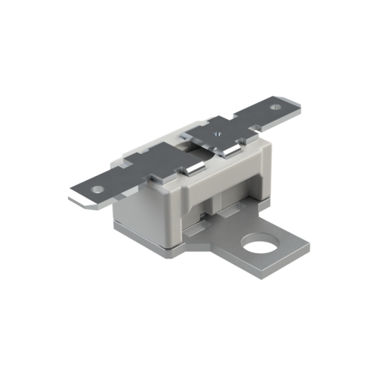
The advantages of Minimelt II
Details
Technical Data
fixed Thermal Link
The thermal link „Minimelt II“ is approved according to DIN EN 60 691 and is suitable for the following conditions:
| Ambient conditions: | The thermal link is intended for use in normal atmospheric conditions. |
| Circuit conditions: | The thermal link is intended for use in resistive circuits only. |
| Proof tracking index: | PTI > 250 |
Characteristic Currents | VDE | *) cURus |
|---|---|---|
| Rated current | Ir | 15 A |
| Interrupting current | Ib | 22,5 A |
| Transient overload current | Ip | 225 A |
| Rated Voltage | Ur | 230 V |
| *) cURus = UL / CSA |
Note concerning type number
The complete number will be issued by the manufacturer together with a drawing based on the specific design.
Type designation code: e.g.
| 155131. | 301 | 01 | 7 | B |
| 1 | 2 | 3 | 4 | 5 |
1 Type (identifies design)
2 Variants suffix (identifies dimensions, terminals, fixing arrangements)
3 Date of production – week
4 Date of production – year
5 Code for manufacturing plant
Special instructions
The thermal link should neither be coated or potted nor be used in impregnated windings.
The thermal link is a non repairable part. In case of replacement an equivalent thermal
link with the same type number and rated functional temperature Tf should be used,
mounted in exactly the same way. Th does not relate to the ambient temperature
only but to the temperature measured at the mounting plate close to the thermal element.
According to UL/EN 60 691/10.6 in the case of a fault, a rate of temperature change of
> 1K per minute is required between Th and Tf +5K to trip the thermal link.
Characteristic Temperature
Tf ... Rated functioning temperature
Th ... Holding temperature according to DIN EN 60691 (measured at mounting plate close to the thermal element)
Tm ... Maximum temperature limit
Tf-10 K | Th | Tm |
|---|---|---|
| 206°C | 170°C | 500°C |
| 229°C | 205°C | 500°C |
| 260°C | 230°C | 500°C |
| 298°C | 260°C | 500°C |
| 318°C | 280°C | 500°C |
Tolerance for Tf acc. to VDE 0821 / EN 60 691 - 10 °C
Applications
Properly installed, the thermal link type 155 131 may be used for applications where a maximum temperature must not be exceeded, for example in coffee makers, irons, dishwashers, dryers and to protect electric heating elements.
Structure and mode of operation
The thermal link has a melt solder insert in the mounting plate which is in direct thermal contact with the surface that is to be monitored. When the preset temperature is reached, the solder melts causing a pin to move which results in the electrical contacts opening. Resetting is not possible.
Mounting requirements
During installation, compliance with all relevant electrical requirements must be ensured with special regard to insulation resistance, dielectric strength, creepage distances and clearances both under normal conditions and in case of a fault, as specified in the relevant equipment standard, for example DIN VDE 0700 (IEC 60335-1).
The requirements in the application note in appendix A of the DIN VDE 0821 EN 60 691 shall be taken into consideration. When mounting the thermal link the following requirements shall be observed:
- the terminals shall be used for internal connections only;
- the switch mechanism inside the ceramic housing must not be touched by any tools or similar objects to avoid damage and possible malfunctions.
Advantages
- current supply up to 15 A
- protected contact system, no cover cap required
- very fast response time thanks to integrated solder strut in the base plate
- constant response time for different installation positions
- easy mounting
- high continuous operating temperature Th
- high quality through fully automated production
Approbation
The Approbation List will be provided upon request.
Applications
Downloads
List of all available downloads.
| Download file | Version | Extension | Size | |
|---|---|---|---|---|
|
Data sheet_155131
|
489 KB | Download |
